

Panasonic AV-HS6000 2 M/E Live Switcher Main Frame & Control Panel (Dual Redundant Power Supplies)
Key Features
- Main Frame & 2 M/E Control Panel
- Redundant Power Supply Configuration
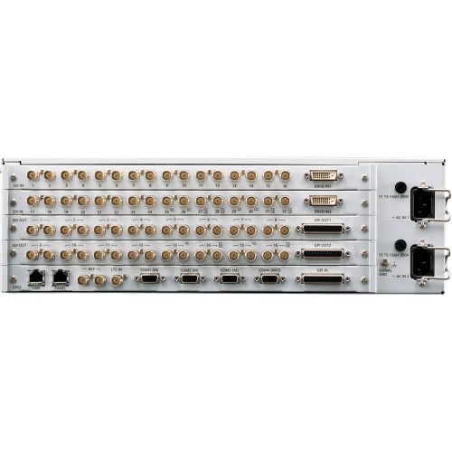
- 32 HD-SDI and 2 DVI-D Inputs
- 16 Outputs Each Mirrored on 2 SDI Outs
This configuration of the Panasonic AV-HS6000 2 M/E Switcher includes the main frame of the switcher, featuring the input/output connectors and processing engine, and a 2 M/E control panel, both in a dual redundant power supply configuration.
This configuration of the Panasonic AV-HS6000 2 M/E Switcher includes the main frame of the switcher, featuring the input/output connectors and processing engine, and a 2 M/E control panel, both in a dual redundant power supply configuration.
The main frame offers 32 HD-SDI inputs, two DVI-D inputs for incorporating computer sources, and 16 output channels each mirrored on two SDI outputs. The main frame supports video resolutions up to 1080p at 10-bit 4:2:2 in YUV color space, and up to 1080p 8-bit 4:4:4 in RGB color space. It also accepts VESA resolutions up to 1600 x 1200 for a 4:3 aspect ratio output and 1920 x 1200 for a 16:10 output.
The control panel features two sets of bus selector buttons, crosspoint buttons, T-bars, a joystick, transition keys, display panel, and more. It also additionally supports the optional AV‑HS60C3G touchscreen menu panel, which allows quick menu operation as well as control of other functions via physical buttons and rotary encoders.
Panasonic AV-HS60U2P Main Frame w/ Dual Power Supply for AV-HS6000 Switcher
The AV-HS60U2P Main Frame w/ Dual Power Supply for AV-HS6000 Switcher from Panasonic features the input and output connectors and processing engine that drives the AV-HS6000 2 M/E switcher. It features 32 HD-SDI inputs, along with two DVI-D (digital only) inputs for incorporating content from computer sources. It will support video resolutions up to 1080p at 10-bit, 4:2:2 in YUV color space, and up to 1080p 8-bit, 4:4:4 in RGB color space. Additionally, it will accept VESA computer resolutions up to 1600 x 1200 for 4:3 and 1920 x 1200 for 16:10.
It features 16 output channels, with each output channel mirrored on two SDI outputs. Not only can these outputs be used for an isolated, program, or aux feed, it is also possible to combine up to 16 ISO channels and send to one display using the MultiView function. Additional display arrangements are also possible, including a “squeeze mode” which reduces the image size to fit audio levels and other data around the outside. A total of 4 channels may be used in conjunction with the MultiView function.
The system features two mix and effects (M/E) buses with fades, transitions, and other effects possible. Additionally, the switcher features both upstream and downstream keyers (USK and DSK) for filling in black space, logo and graphic insertion, and compositing. Frequently used effects, setting, video clips, and still images can be save to the internal memory for later recall during a production.
The AV-HS60U2P is designed to be operated using the AV-HS60C1P/AV-HS60C1E or RAV-HS60C2P/AV-HS60C2E control panel. In addition, software plug-ins allow operation over an IP network or using certain Panasonic and third-party RS-422 serial devices. In addition, the AV-HS60C3G Menu Panel is required to access and change settings locally at the switcher.
This version of the AV-HS60U features dual redundant power supplies. This way , if the first power fails the second will instantly takeover so that there is no interruption in service.
Connectivity
32 HD-SDI and 2 DVI Inputs
Despite being enclosed in a 3RU frame, the mainframe provides wide variety of inputs/outputs with frame synchronizer, format converter, and color correctors:
- Colors can be adjusted to correspond to different video source formats, camera properties, and displays
- All inputs feature a 10-bit frame synchronizer
- 8 inputs are equipped with color correctors
- 4 inputs are equipped with upconverters
- Signals can be delayed by up to 8 frames
16 SDI Outputs with 2 Outputs Per Channel
Each output features two mirrored SDI connectors
- 4 outputs are equipped with color correctors
- 2 outputs are equipped with downconverters
4-Channel MultiViewer Function
An independent 4-channel MultiViewer output function is provided that features a total of 9 patterns, and allowing up to 16 images to be displayed on one screen:
- MultiViewer can be selected from a total of 9 patterns, including: 4 split, 5 split (2 patterns), 6 split (2 patterns), 9 split, 10 split (2 patterns), and 16 split
- Source names, tallies, audio level meters, clock, and safety markers can be displayed
- Squeeze Mode can be selected to place the source name and level meter placed outside of the image
Mix and Effects (M/E)
Diverse DVE Transitions
In addition to wipe, mix, and cut transitions, DVE (digital video effects) transitions with 2-channel 3D DVE, such as size reduction and sliding, can be performed. Image rendering effects such as mosaic or defocus are also possible4 channels of 3D DVE and 2 channels of 2D DVE systems are provided to support background and keys for each M/E bus
Multiple Keyers
The system feature a variety of keyers to promote creative live content creation:
- Chroma Key: Thanks to the proprietary Primatte algorithm, real time and high quality key compositions are possible
- PinP (Picture-in-picture): 4 channels per M/E bus (8 channels total)
- Key Preset: The Key Preset function allows memorization and recall of the a key’s particular settings. 4 settings for each channel of key and 4 settings for each channel of DSK (downstream key) can be registered
- Upstream Key (USK): 4 channels of USK are provided for applications such as adding the CG elements to fill the gap when inserting a 4:3 image in 16:9 frame
- Downstream Key (DSK): 4 channels DSK are available — these can be assigned to PGM1 or PGM2 output
Memory Functions
The memory function allows mixer, video, and effects settings to be stored for later recall. It is designed to save time, allowing the operator to quickly engage frequently used settings and effects during a live broadcast where there is little or no margin for error
- Shot Memory: This function recalls background transition patterns or other video effects, including PinP size, position, border width, and key
- Event Memory: This function allows continuous image effects to be to registered and played back in a timeline
- Macro Memory: This function allows the recording and playback of a series of operations on the Control Panel. It can also record and playback setting information, such as input/output and keyers. Macro memories can be played back by assigning them to the cross point buttons, such as macro bus, PGM, and PST
- Video Memory: Moving image (Clip) and still image (Still) can be recorded for 4 channels each for later reuse as video sources. A maximum 60 seconds of moving images can be saved in standard mode, and Maximum 30 seconds in high image quality mode
Intuitive Switching
- Multi-Selection Panel: A color panel that can display thumbnail images with high visibility
- Animation Wipe: With moving images (clip) and still images (still) recorded in video memory, it is possible to create animation wipes
System Scalability
- 16 AUX buses are provided. MIX transition is available from the AUX1 to AUX4 buses
- The system can be operated remotely from a PC via a network connection
- Supports interoperability with various third-party software plug-ins and connectivity with other devices. In addition to pre-installed plug-in software, customized software solutions can be created using the SDK
Included Plug-in Software
Serial Control Software
This software controls switching and transition of crosspoint with GVG200-compliant external controllers and editors using an RS-422 serial interface — external controllers and control software are available separately
IP Connected AUX Bus Control Software
This software controls switching from a VS-R45 remote operation panel to crosspoint via an IP network
Serial Tally Software
This software provides tally output and source names to an external tally display and I/F, and features UMD protocol v3.1 support. Tally is connected via an RS-422 serial interface
SDI Input
- Lines: 32
- Connectors: 32 x BNC female
- SDI channels 27, 28, 31, and 32 are equipped with up-converters
- SDI channels 25 to 32 are equipped with color correctors
Signal Standards HD-SDI
- SMPTE292M (BTA S-004) standard compliant
- 0.8 V (p-p) ±10% at 75 ohm
- Automatic equalizer for runs more than 328′ (100 m) — when 1.5 Gbps/5C-FB cable is used
Signal Standards SD-SDI
- SMPTE259M standard compliant
- 0.8 V (p-p) ±10% at 75 ohm
- Automatic equalizer for runs more that 656′ (200 m) — when 5C-2V cable is used
DVI Input
- Lines: 2
- Connectors: 2 x DVI-D
- Supported Resolutions (Computer): XGA (1024 x 768), WXGA (1280 x 768), SXGA (1280 x 1024), WSXGA+ (1680 x 1050), UXGA (1600 x 1200), WUXGA (1920 x 1200)
- Vertical Frequency (Computer): 60 Hz Supported Video Formats: 1080/59.94p, 1080/50p, 1080/59.94i, 1080/50i, 720/59.94p, 720/50p
- Note:
- Cable lengths up to 16.4′ (5 m) are supported
- A DVI-I cables are not supported
- HDCP is not supported
SDI Output
- Lines: 16 — two distributed outputs per line
- Connectors: 32 x BNC female
- Assignments: ME1PGM, ME1PVW, ME1CLN, ME1KEYPVW, ME2PGM, ME2PVW, ME2CLN, ME2KEYPVW, DSKPGM1, DSKPGM2, DSKPVW1, DSKPVW2, DSK1CLN, DSK2CLN, DSK3CLN, DSK4CLN, SEL KEYPVW, MV1 to MV4, and AUX1 to AUX16
Signal Standards HD-SDI
- SMPTE292M (BTA S-004) standard compliant
- 0.8 V (p-p) ±10% at 75 ohm
Signal Standards SD-SDI
- SMPTE259M standard compliant
- 0.8 V (p-p) ±10% at 75 ohm
Video Formats
- SD: 480/59.94i, 576/50i
- HD: 1080/59.94i, 1080/50i, 720/59.94p, 720/50p, 1080/24PsF, 1080/23.98PsF, 1080/25PsF
Signal Processing
- Y: PB: PR: 4:2:2, 10-bit
- R:G:B: 4:4:4: 8-bit
Mix / Effect Buses
- 2 ME
Synchronous Terminal
Reference Input
- Connectors: 2 x BNC female — input with loop-through
- Supports same field frequencies as those of the system formats supported:
- In Genlock Mode: Black burst or tri-level sync (with loop-through)
- Note:
- If the loop-through output is not used, 75 ohm termination is required
- In the 1080/24PsF and 1080/23.98PsF formats, only Genlock mode supported In the 1080/23.98PsF format, black burst signals with 10 Field ID (SMPTE318M compliant) or Tri-level Sync signals are supported
- In the 1080/24PsF format, Tri-level sync signals supported
- In internal sync mode black burst signal is output through both connectors
LTC Input
- Connector: BNC female
- Impedance: 1 kohm
- Level: 1 to 2 V (p-p)
Video Delay
- 1 Line (H): When the frame synchronizer is set to “Off” and the upconverter is set to “OFF”
- 1 Frame (H): When the frame syncronizer is set to “ON”, or the upconverter is set to “ON”
-
Note: When the signals have passed through PinP, DVE, MultiView, down-converter, or DVI-IN, a maximum delay of 1 frame is applied in each case
Control Terminal
LAN Terminal
- Connector: 1 x RJ-45
- Compatible with 100Base-TX and AUTO-MDIX — for IP control
- Supported Cable: CAT5E or better, up to 328′ (100m) — STP (Shielded Twisted Pair) cable recommended
PANEL Terminal
- Connector: RJ-45
- Compatible with 100Base-TX and AUTO-MDIX — for Control Panel (AV-HS60C1/AV-HS60C2) connection
- Supported Cable: CAT5E or better, up to 328′ (100m) — STP (Shielded Twisted Pair) cable recommended
Serial Interface
- Connectors: 4 x D-sub 9-pin female
- Terminals 1 to 3: For master connection to control external devices
- Terminal 4: For master/slave connection to control external devices
GPI In/Out
- Connectors: 3x D-sub 25-pin female
- Terminal 1
- GPI Input: 18 inputs, general-purpose, photocoupler sensing
- Alarm Output: 1 output, open collector output (negative logic)
- Terminal 2 and 3
- GPI Output: 48 outputs, selectable general purpose or tally — open collector output
Based on 0 reviews
Only logged in customers who have purchased this product may leave a review.
You may also like…
-
Professional Video Switchers
Blackmagic Design ATEM Television Studio Pro HD Live Production Switcher
 Professional Video Switchers
Blackmagic Design ATEM Television Studio Pro HD Live Production Switcher
Key Features
- 8-Channel SDI/HDMI Switcher
- NTSC/PAL, HD, Computer Signal Compatible
- 10-Channel Digital Audio Mixer
- Built-In Front Panel Controls
Designed for broadcasters and A/V professionals, Blackmagic Design’s ATEM Television Studio Pro HD Live Production Switcher is an 8-input live production switcher with integrated control panel. Four of each HDMI and SDI inputs are available on the rear of the chassis, with both sets of inputs supporting SD and HD resolution
SKU: SWATEMTVSTU/PROHD -
Professional Video, Studio & EFP Equipment, Production Switchers & Controllers, Professional Video Switchers
Panasonic AV-HS7300 Live Switcher Main Frame & Control Panel
 Professional Video, Studio & EFP Equipment, Production Switchers & Controllers, Professional Video Switchers
Panasonic AV-HS7300 Live Switcher Main Frame & Control Panel
The control and menu panels support accurate switching and intuitive operation and boast a multitude of functional inputs and outputs as well as keyers and DVEs that support a variety of performances.
SKU: AV-HS7300 -
Professional Video, Used
Evertz X-0401 X-Series 4×1 Video And Audio Router
Features
- Supports SMPTE ST 424M (3GB/s), SMPTE ST 292-1 (1.5GB/s), SMPTE ST 259 (270, 360 or 540MB/s) and DVB-ASI video signals
- Switch point is fully controllable from the front panel
- Video input presence detection displayable on the front panel
- Front panel or remote control panel version available. Second control panel can be ordered for any version
- Programmable source input names available on the front panel
- Bypass verification test using main menu
- Programmable tally output bus
SKU: X0401X -
Professional Video, Studio & EFP Equipment, Production Switchers & Controllers, Professional Video Switchers
Panasonic AV-HS450N HD/SD-SDI Switcher with Dual-Screen Multiviewer Display
 Professional Video, Studio & EFP Equipment, Production Switchers & Controllers, Professional Video Switchers
Panasonic AV-HS450N HD/SD-SDI Switcher with Dual-Screen Multiviewer Display
Key Features
- HD/SD-SDI Inputs: 16
- HD/SD-SDI Outputs: 4
- Two DVI-D Outputs
- 10-Bit Processing
The Panasonic AV-HS450N is a 16+ input HD/SD-SDI Switcher with Dual-Screen Multiviewer Display. The two-rack sized switcher comes equipped with 16 HD/SD-SDI inputs and four HD/SD-SDI outputs, along with two DVI-D outputs. The switcher’s sophisticated full 10-bit HD processor produces unmatched image quality.
SKU: AV-HS450

Related products
-
Professional Video, Studio & EFP Equipment
Blackmagic Design Micro Studio Camera 4K
Features:
- Active Micro Four Thirds Lens Mount
- Resolutions Up to 3840×2160 at 30 fps
- 10-Bit 4:2:2 6G-SDI Video I/O
- Ultra-Compact Design
- SDI Remote Control Protocols
- PTZ Serial Output & B4 Data Link
SKU: Micro Studio Camera 4K -
Studio & EFP Equipment, Production Switchers & Controllers, Professional Video Switcher Accessories
Datavideo TBC-7000 Dual Layer Chroma Key / TBC, Dual Channel, Proc-Amp, Frame Sync, Composite (RCA), Y/C
 Studio & EFP Equipment, Production Switchers & Controllers, Professional Video Switcher Accessories
Datavideo TBC-7000 Dual Layer Chroma Key / TBC, Dual Channel, Proc-Amp, Frame Sync, Composite (RCA), Y/C
The TBC-7000 is a dual channel TBC featuring a dual layer Chroma key for creating background and foreground video layers. Each channel features separate functionality.
SKU: TBC-7000 -
Professional Video, Studio & EFP Equipment, Production Switchers & Controllers, Professional Video Switcher Accessories
Blackmagic Design GPI & Tally Interface for ATEM Production Switchers
 Professional Video, Studio & EFP Equipment, Production Switchers & Controllers, Professional Video Switcher Accessories
Blackmagic Design GPI & Tally Interface for ATEM Production Switchers
Key Features
- Displays Tallies for Video Signals
- Indicates On-air Status
- For ATEM Switchers / Videohub Routers
- 8 Contact Closure Inputs & Outputs
The Blackmagic Design GPI & Tally Interface for ATEM Production Switchers is designed to display tallies to indicate the on-air status of video signals. It features 8 contact closure inputs and 8 contact closure outputs for connecting to ATEM switchers and Videohub routers for operation.
SKU: SWTALGPI8 -
Studio & EFP Equipment, Production Switchers & Controllers, Professional Video Switcher Accessories
Datavideo PD-4A Power Distributor with Redundant Power Supply
 Studio & EFP Equipment, Production Switchers & Controllers, Professional Video Switcher Accessories
Datavideo PD-4A Power Distributor with Redundant Power Supply
The Datavideo PD-4A Power Distributor comes with a redundant power supply, which is a second power supply that provides power just in case the first one fails. This PD-4A Power Distributor lets you use a single power cord with no additional power supplies for the switcher, processor, and other devices that operate on 12VDC.
SKU: PD-4A -
Professional Video, Studio & EFP Equipment, Studio & EFP Camera Accessories
Pro-X XP-DV-S Adapter V-mount voeding voor Sony DV camera’s
 Professional Video, Studio & EFP Equipment, Studio & EFP Camera Accessories
Pro-X XP-DV-S Adapter V-mount voeding voor Sony DV camera’s
XP-DV-S Adapter cable to connect a Pro-X Li-ion battery to a Sony DV camera. The cable contains a powerport 12V connection for powering a lamp or mic. Receiver at the end is a picture that is clicked on the camera. Compatible with (among others) the following Sony cameras: NEX-FS100 HVR-Z7U HVR-HD1000U HVR-V1U HVR-Z1U HDR-FX1 VX2000 / 2100 PD100 / 150/170SKU: XP-DV-S


There are no reviews yet.